Size Your Living Room Like a Pro: Align Dimensions to Material Modules to Cut Waste and Control Costs
Designing a “perfect” living room isn’t just about aesthetics and furniture placement. On large residential programs, the fastest way to shave cost and reduce site risk is to size rooms so they land cleanly on standard material modules.
When your living room width and depth align with common tile sizes, gypsum board sheets, and ceiling grid spacing, you cut far fewer pieces, order fewer extras, and simplify installation.
This guide distills a field-tested workflow you can apply during schematic planning—complete with dimensions, module references, and trade-offs—so your drawings translate to efficient procurement and clean execution.
Start with hard constraints (code and space standards)
Before optimizing to material modules, confirm minimums that govern habitability and clearances.
In the United States, the International Building Code requires at least one habitable room of 120 ft² (approx. 11.2 m²) per dwelling unit; see the 2021 edition’s provision in IBC Section 1208.3 (ICC, 2021).
In the UK, permitted development homes must meet the Nationally Described Space Standard (NDSS); this policy mandate was clarified in 2020 by the UK government in “Permitted development homes to meet space standards”.
Australia’s typical benchmark sets minimum ceiling heights of around 2.4 m for habitable rooms in common interpretations of the NCC; see this overview of NCC ceiling height benchmarks.
Use these as floor constraints. Your goal is to go above minimums while sizing to modules so that finishes install with minimal cutting and fewer seam lines.
The modular grid you should design to
Modular coordination has existed for decades. The principle is simple: choose base modules (and their multiples) so components interface cleanly.
A classic reference is ISO 2848 modular coordination, which establishes a 100 mm base module with preferred multiples like 300, 600, and 1200 mm. For a practical explainer, the Designing Buildings Wiki’s summary of modular coordination is helpful.
Practically, this gives us dimension “beats” to design around for living rooms: 3600, 4200, 4800, 5400, and 6000 mm. These hit commonly available tile, board, and ceiling modules with minimal edge cutting.
Map room dimensions to real material modules
The following modules are widely available in international markets and are useful targets during schematic planning.
Floor tile modules
- Common: 600×600 mm, 600×1200 mm, 800×800 mm; large formats also exist. See manufacturer overviews like Orientbell’s tile sizes.
- Design implication: prefer widths/depths that are whole-number multiples of your chosen tile module; avoid narrow perimeter slivers by adjusting the room dimension by one tile increment when needed.
Gypsum board (drywall) sheets
- Metric and imperial families co-exist; in most markets you’ll find 1200×2400 mm as a baseline module, with longer variants (2700/3000 mm). Manufacturer datasheets (e.g., USG Middle East gypsum board TDS) confirm 1200 mm widths and 2400+ mm lengths.
- Design implication: coordinate ceiling height to standard board lengths to reduce horizontal cut lines and butt joints.
Suspended ceiling grids
- Standard commercial/residential grid spacing commonly uses 600×600 mm or 600×1200 mm modules. A technical reference to layout and framing practices is Armstrong’s Hanging & Framing Flat Ceilings — Technical Guide (2021).
- Design implication: align room spans to 600 mm increments so perimeter trims are generous, not slivers, and lighting/HVAC diffusers land on module centers.
Engineered wood/SPC planks
- Typical planks run roughly 184–235 mm wide and 1220–1524 mm long, depending on product lines. Design implication: while you don’t strictly size rooms to plank lengths, you should avoid widths that force narrow “rips” at the far wall; 100 mm increments help.
Plywood/MDF panels (built-ins, feature walls)
- Standard sheet modules are 1200×2400 mm; coordinating wall widths/heights reduces panel cuts and waste. This is particularly valuable for feature wall systems and integrated storage.
Recommended living room dimension bands by module grid
| Target module family | Suggested dimension bands (mm) | Why it works |
|---|---|---|
| 600 mm tile grid | 3600 / 4200 / 4800 / 5400 / 6000 | Whole tile counts, symmetric perimeter joints |
| 1200 mm board/ceiling grid | 3600 / 4800 / 6000 | Fewer seams; boards and grids align |
| Mixed modules (tile 600, board 2400) | 4200 / 4800 / 5400 | Satisfies both floor and wall modules |
These are not absolutes; they’re “sweet spots” that reduce cutting while preserving furniture planning flexibility.
A step-by-step workflow you can implement tomorrow
1. Choose your module family early.
- Decide metric vs. imperial at the outset based on project location and supplier availability. If you expect metric tiles and boards, design to 100/300/600/1200 mm beats. If imperial modules dominate (e.g., 2×2 ft ceilings, 4×8 ft boards), convert dimensions and keep the grid logic.
2. Set a schematic grid at 600 mm.
- Establish a 600 mm reference grid in your CAD/BIM template. Dimension the living room’s width and depth to land on preferred multiples (e.g., 4800×3600 mm), then iterate to accommodate furniture clearances.
3. Floor module test: run a tile count simulation.
- Block in your intended tile size (e.g., 600×600 or 600×1200). Ensure whole tile counts wall-to-wall with balanced perimeter joints. If you see 100–150 mm slivers on one side, adjust the room by ±300–600 mm or consider a centered pattern.
4. Wall and ceiling coordination.
- Check ceiling height options (e.g., 2400, 2700, 3000 mm). Aim to use full board lengths vertically, minimizing horizontal joints. For dropped ceilings, check 600×600 grids and confirm feature lighting falls on grid centers.
5. Furniture clearances and circulation.
- Overlay furniture and walking paths. If a sofa grouping requires an extra 300 mm to avoid tight circulation, add it—but still try to preserve module alignment on the opposite dimension.
6. Pre-bid takeoff simulation.
- Extract a quick material takeoff by module count: tiles per row/column, boards per wall, grid panels per ceiling. Use this to identify cutting hotspots before design lock.
7. Supplier alignment and availability confirmation.
- Verify that your chosen modules are readily available in your target market. Manufacturer overviews like Orientbell’s tile sizes help confirm floor tile options, and gypsum board datasheets like USG Middle East TDS confirm board sizes.
8. Site-scale validation.
- Validate on structural grid and MEP coordination. Ensure columns, chases, and diffusers don’t force awkward cuts at perimeters. Where conflicts arise, adjust by one module step rather than bespoke fragments.
Worked examples: quantify the gains
Example 1: tile layout — 4720 mm vs. 4800 mm width on a 600×600 mm module
- At 4720 mm width, 7 full tiles (7×600 = 4200 mm) leave 520 mm; you’ll split that into two 260 mm edge strips or force asymmetric cuts.
- At 4800 mm width, 8 full tiles land perfectly with balanced joints and no narrow strips.
- Result: moving from 4720 to 4800 mm avoids multiple perimeter cuts and improves installer efficiency. It also improves aesthetics by eliminating skinny tiles.
Example 2: ceiling height — 2450 mm vs. 2400 mm using 1200×2400 mm boards
- At 2450 mm, you need a horizontal cut and a 50 mm strip, plus an extra seam.
- At 2400 mm, full board heights install without horizontal joints.
- Result: a 50 mm height reduction can remove an entire line of cuts and butt joints, cutting installation time and simplifying finishing.
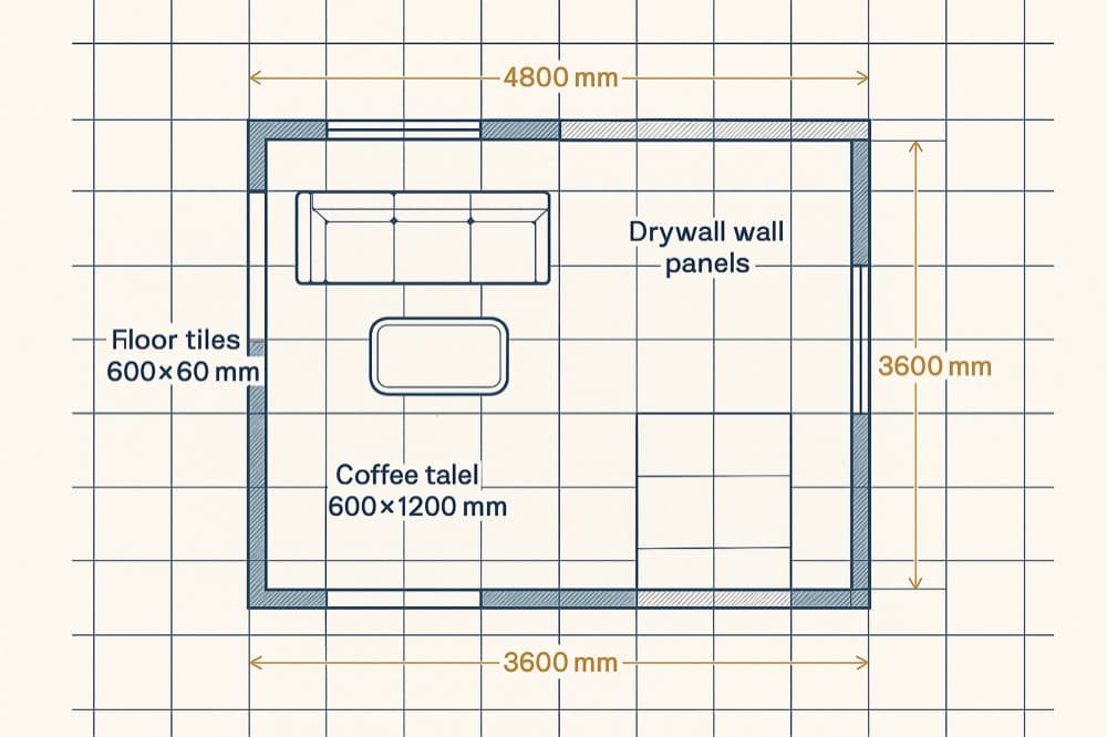
Example 3: dropped ceiling grid — 3600×4800 mm room with 600×600 mm modules
- Width 3600 mm = 6 modules; depth 4800 mm = 8 modules.
- Benefits: luminaires can be centered on modules; diffusers land cleanly; no perimeter slivers; installer can use standard grid layouts referenced in Armstrong’s technical guide.
Regional decision-making: metric vs. imperial modules
- Codes and practices vary, but the module mindset is universal. US projects often use 4×8 ft board logic and 2×2 or 2×4 ft ceiling panels tied to imperial grids. EU/CN projects commonly use 1200×2400 mm boards and 600×600 mm ceiling grids. The module strategy is grounded in long-standing coordination principles; the ISO committee catalogue for ISO 2848 modular coordination and the Designing Buildings overview of modular coordination outline the 100/300/600/1200 mm preference widely adopted in practice.
- Minimum areas and heights still apply. In the UK context, the NDSS mandate reiterated in 2020 (“Permitted development homes to meet space standards”) ensures adequate space provision at a dwelling level. In the U.S., IBC 2021 Section 1208.3 sets a baseline for one habitable room’s area, and Australia’s NCC interpretations maintain 2.4 m ceiling height benchmarks for habitable rooms.
Pitfalls and trade-offs (and how to manage them)
Furniture-first blind spots
- Over-optimizing for furniture can accidentally land dimensions off-module, causing expensive edge cuts. Remedy: iterate in 300–600 mm steps to keep both furniture and modules in harmony.
Over-customization on feature walls
- Irregular geometries can explode panel cutting. If you must break the grid for a bay or niche, do it in whole-module increments (e.g., add 600 mm) or isolate the custom feature from main wall runs.
Mixed-material clashes
- Floor tile centered patterns may fight wall panel seams. Resolve by prioritizing the floor module first, then adjust wall seam locations; ceiling grids can typically accommodate with minor perimeter trims.
Availability assumptions
- Assuming a module exists locally can lead to procurement surprises. Always confirm manufacturer supply in your region—boards and tile series differ by market.
Tolerances and on-site reality
- Structural deviations, plaster build-ups, and skim coats shift clear dimensions by 10–20 mm. Protect yourself by designing to modules with generous perimeter allowances and specifying acceptable trim ranges.
Implementation checklist (ready to use)
- Decide metric vs. imperial modules at project kickoff; set your CAD/BIM grid to 600 mm or 2 ft.
- Target living room width/depth at 3600/4200/4800/5400/6000 mm bands; confirm with your selected floor tile module.
- Coordinate ceiling height to board lengths (e.g., 2400/2700/3000 mm); eliminate horizontal joints where possible.
- Run tile and board count simulations; correct narrow-perimeter strips by adjusting room dimensions in 300–600 mm increments.
- Place primary luminaires and diffusers on ceiling module centers; avoid slivers at edges.
- Validate supplier availability for chosen modules using manufacturer datasheets (e.g., USG gypsum board TDS) and tile size overviews (e.g., Orientbell).
- Document acceptable perimeter trim ranges and installation tolerances in the drawings.
Why this works economically
Modular alignment reduces cutting, seam count, and installation complexity.
In modular interiors more broadly, firms report substantial budget advantages when systems are designed to standard modules; for example, a 2024 insight from DIRTT describes a project closing more than $500,000 under budget due in part to modular efficiencies, see “The Value of Prefabricated Modular Construction”.
While living room-scale savings will be smaller, the same mechanics apply: fewer cuts and seams translate to less labor time, lower risk of rework, and leaner material orders.
Closing next steps
Submit your floor plans to ChinaBestBuy for a module-aligned, factory-direct sourcing quote tailored to your living room specifications.